LED Wall Display
Posted 2008-01-25 Tweet
More pictures are available in the Photo Gallery
What is it?
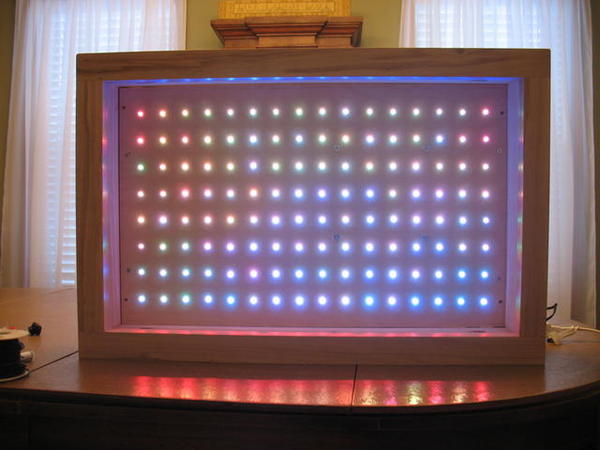
It could be art? Decoration? Science? Any or all of the above. It is however a wall hanging made with 128 tri-color LEDs. Each LED can show one of 4913 colors. It is programmed to show different patterns on the screen, like a 21st century lava lamp.
The idea
I built this project for my Dad for Christmas 2007. The idea was inspired as an extension to the LED Table Project. In combination with seeing the amazing effects from the LED Table, I also saw several projects online where people had built LED arrays to make interesting displays.
The main inspiration for this project is the HypnoCube project. It is a similar circuit but in a 3D configuration. My project has twice the number of LEDs, so the circuitry is essentially doubled.
The main idea in the end was to build a LED display out of an array of tri-color LEDs. I ended up with a 16 x 8 tri-color LEDs, which is essentially an array of 48 x 8 single color LEDs.
Once built, it should be programmed to display various patterns to act as an art display hanging on a wall.
Building
Most of the details will be under the Technical Details section, but a brief overview of the steps:
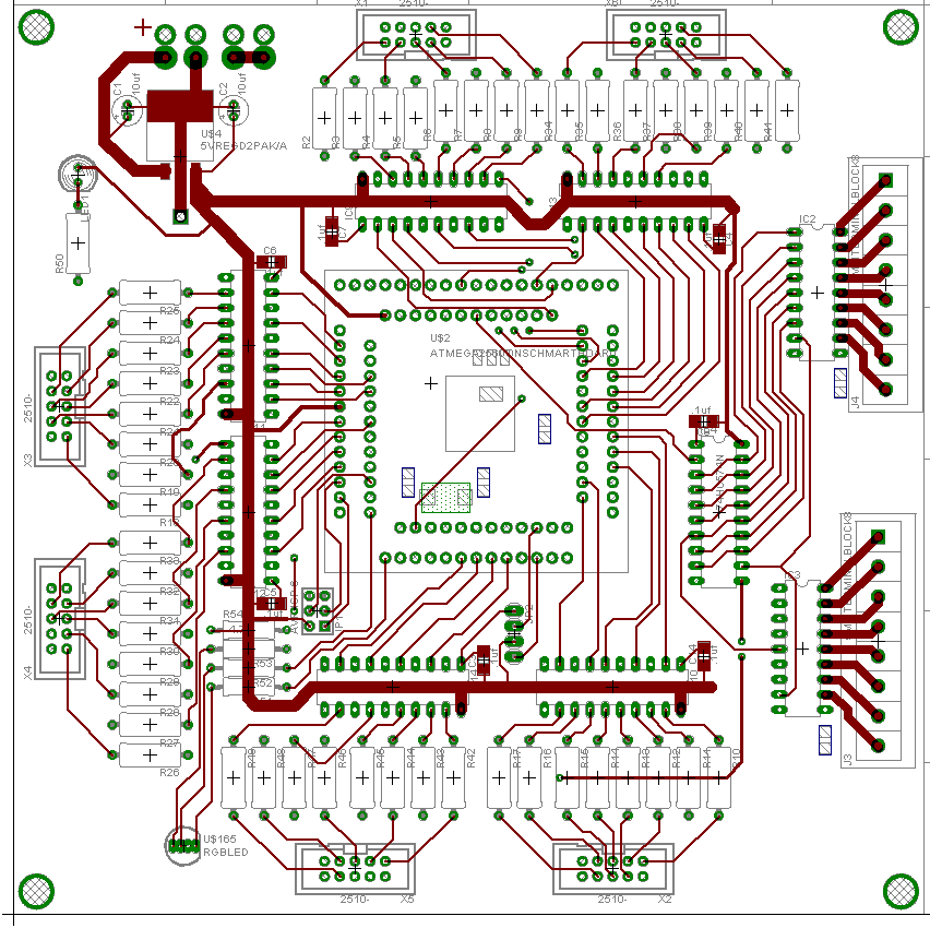
- Design the circuit in Eagle Layout Editor
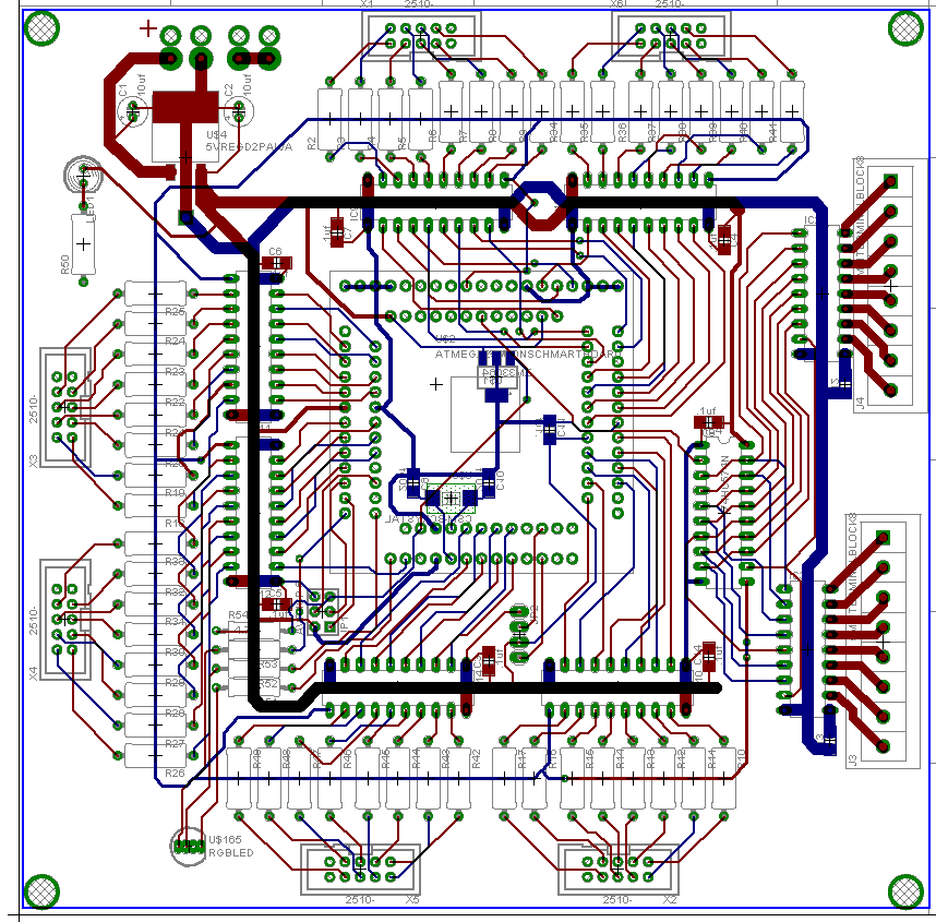
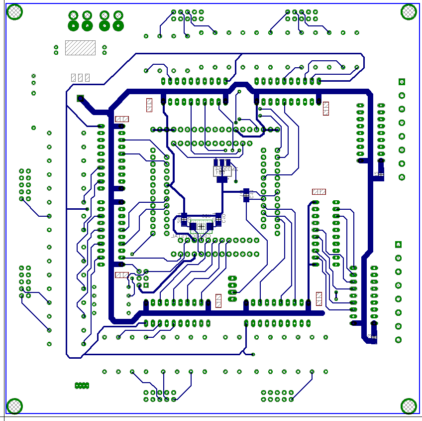
- Lay out the circuit board in Eagle Layout Editor
- Order the circuit board to be produced and the electrical parts
- Cut the circuit board into the 130 individual small boards for the LEDs
- Solder the 128 LEDs to their boards and the interconnect wiring
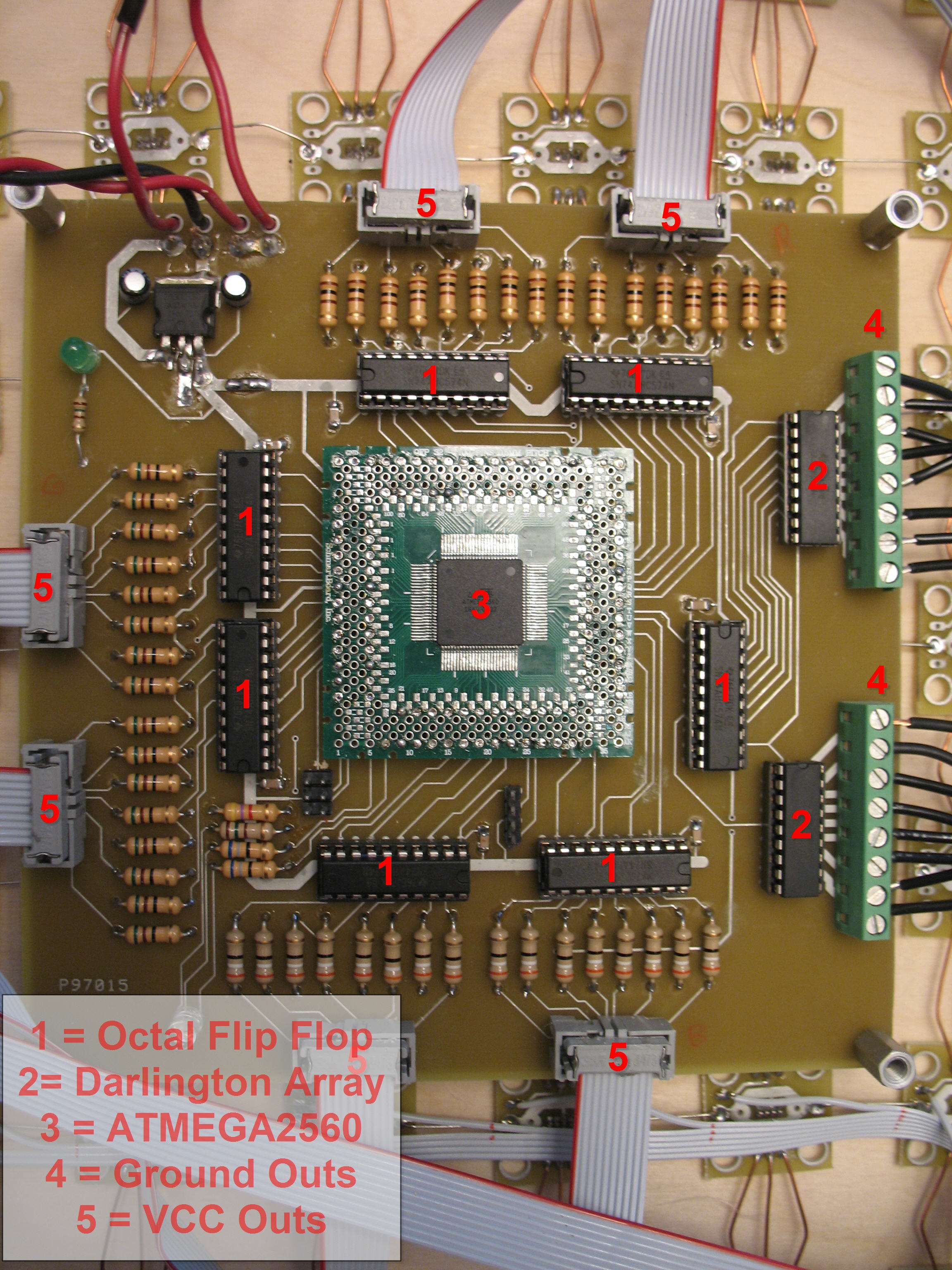
- Assemble the main circuit board
- Write the code
- Build the physical frame
- Assemble all of the pieces
Technical Details
I would be happy to provide the eagle schematic and board files, as well as any information about the code that you like. Everything here is presented with no warranties whatsoever. Just send me an email.
- Schematic – schematic is here.
- Code: wall_display.c and Makefile.
- Board: Board.png, board-bottom.png, board-top.png
- Eagle Schematic File – schematic is here.
- Eagle Board File – board is here.
- Parts Details
Theory of Operation
The LED display works on the POV (persistance of vision) effect of the human eye. The LEDs each stay on for a very brief period of time, but the human eye and brain together make it appear as if the LEDs stay on the entire time. Because of this effect, the LEDs only need to be lit up for a short time period, which gives us the option to scan through them very quickly. This is important because there are 16 * 8 * 3 = 384 LEDs in the display. Obviously our microcontroller does not have 384 outputs, nor did I want to create a control board with 384 transistors and individual wiring outputs. So the solution is to create a matrix of LEDs. Each row (8) has all of its negative LED terminals tied together, and each column (16 * 3 = 48) has all of its positive terminals tied together. 48 is a feasible number of outputs for a 8 bit microcontroller. Now each row of LEDs can be individually controlled, so all we have to do is scan through the 8 rows in quick succession turning on the appropriate LEDs in each row for the appropriate amount of time, and we have a big colored LED display.
Each LED is set up for 17 levels of brightness, where 0 is off, and 16 is the brightest. For each row, there are 17 individual time periods. At the beginning of the row loop, all the LEDs in the row are turned on, and each is turned off when a counter reaches its brightness level. Once the counter hits 16, the next row is activated. This is all interrupt driven, and is automatic.
The main program loop is simply responsible for setting the color values into an array to be used by the interrupt driven LED code. Each section in the main program loop implements a different display program.
Videos
Chuck Hays works at Google as an SWE on the Duo team.
Chuck was formerly a Senior SDE at Microsoft working on the Azure AppPlat team.
Chuck lives in Minnesota and is an alumnus of the University of Minnesota with a master's degree in Computer Science & robotics.